The detection section:
 After the input, the light goes through the filtering section which acts like a rainbow and separates colors. In order to get valuable wavelength readings, the goal is to only send one color to the detector. The reality is that no filter can be so precise. The high end laboratory grade units can offer resolution down to 15pm.
There are many aspects to account for in order to get the best possible reading at the detector. One of them is noise. All optical test systems are driven by electronic circuitry. The amount of light left after the filtering section is very low thus the conversion of light into current then into voltage delivers low level signals thus signals very sensitive to noise. To shelter the circuits from the electrical noise, shielding is used around most detection parts. On top of shielding, a chopper motor is used to “slice” the optical signal to a 50 percent duty cycle. The detection circuitry is synchronized with the chopping motor and expects complete darkness then light then darkness and so on. When no signal is expected but some is found, it is known to be noise and can be removed from the displayed results.
Part of the complexity leading to inaccuracy of the OSA is the signal amplification and data processing to cover such large wavelength range. The detector, most times an InGaAs is the last part of the detection section. In the case of an OSA which includes visible light measurement such as the Ando AQ6315E , an InGaAs detector can’t read the 350-700nm range and a detector switching mechanism is included after the monochromator. When reading the low wavelength range, a Silicon (Si) detector is used instead of the InGaAs. Such OSA is not used in telecom measurements as they are expensive, old and the visible range is of little value in such application.
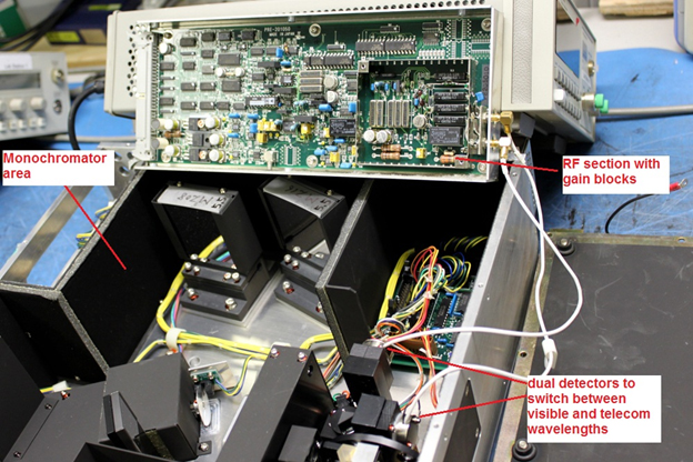
Fig3: Inside an Ando AQ6315E monochromator
The data processing section:
The output of the detection section is an analog signal that must now be digitized. The digitization part could be considered either in the detection or signal processing sections but fact is that to allow for the use of calibration tables and other signal comparison and correction information, the analog optical signal which was converted to electrical voltage by the detector circuit must now be made to a bit stream. We will not expand on this section as this is signal processing like in many products and, although there are differences in quality of such devices, most manufacturer can build this section very well and the readers of this blog likely understand the involved operations fully. Once the optical signal is converted to the desired bit stream, the OSA processing unit kicks in and goes through various algorithms and calibration tables to deliver valuable data where all known unlinearities and filtering issues are smoothed out. The processing also computes numerous pre-programmed functions such as EDFA noise figure testing, automatic peek search, delta between min and max levels, etc.
The user interface section:
This section is the easiest for all to grasp: it is the display, buttons, Ethernet jack and user interface driven by software. In the early days of instrumentation, there was interest in discussing this section as the resolution of displays could be less than the resolution of the filters and detectors; in other words, you could have been focusing on the inaccuracy of the display pixel resolution as opposed to the signal. With the enhancement of displays, this is no longer a consideration. The rest of the user interface is buttons and connectors. It is up to the user to decide which topology of equipment he prefers.