 The signal input section:
There are two very different inputs found in OSAs; free space inputs and fibered inputs. The most known free space (in air) input OSA is the Ando AQ6317B. That OSA is likely the most spread OSA worldwide and was sold in mass volume during the late 1990 and early 2000 which were the boom years of CDWM and Fiber optics based telecom systems. It is fit with an FC front adaptor and can accept either FCAPC or FCPC connector holding any kind of fiber so multimode or singlemode although the fiber used will create some uncertainty in the power readings. The use of free space for the input section offers the great attribute of fiber independence but forces the topology of the monochromator to have the filtering section directly behind the input adaptor. The fibered input OSAs do not have this limitation.
Other OSAs such as the Agilent/HP 86140A and the rest of the Agilent OSA family or the smaller Anritsu MS9710C and previous Anritsu OSA generation have a fibered input which means that the front mating sleeve is directly tied to a fiber right behind it or that the connector in the front of the unit has glass in it and, when so, there is normally a collimator or grin lens right behind it. For best results, the fiber used should be matched with the signal input section fiber. Most of those OSAs were built with singlemode fiber and 62.5um Multimode fibered OSAs such as the Agilent 86141B are rare find on the used market.
So if you are buying an OSA for measurement of “yet to be defined” input signals, you might want to favor a free space OSA while if your measurement is aimed at clearly known signals, a fibered OSA matching the fiber you intend to use will do you just as well as free air. Note that the price between the two input technologies is similar so the selection of one or the other will likely not be based on price.
The filtering section:
Most OSAs are built using a diffraction grating which is a mirror with very precise grooves. That mirror rotates and will, because of the network of grooves and the angle of the mirror at a defined setting, reflect a specific wavelength to the detection area. The beam of light coming to the grating first goes through a slit to cut off a portion of the beam and narrow it so it touches very few grooves of the mirror. That slit defines the spatial width of the input. The narrower the input slit the better resolution of the OSA. In fact, what defines the resolution of an OSA is the input slit, the diffraction grating and the resolution slits. Resolution slits are used to spatially filter the light reflected from the diffraction grating to the detector. This slit is placed into the focal plane of the monochromator and, because the light is already “spatially selected” by the monochromator, this is a good place to make adjustments on the optical resolution and to do so, the user, through resolution settings, selects how much of the light spectrum is allowed to pass and reach the detector. There are a series of output slits for the desired resolutions. A narrow slit selects only a small portion of the light spectra and so we get a high optical resolution but a lower level of light signal. On the other side, a wider slit allows more light in but we get poorer resolution.
The design of most high accuracy OSAs offers a dual pass of the light to the grating thus double filtering. Some offer quad pas and Ando/Yokogawa at some point offered an octo-pass unit (AQ6319) which offered the best wavelength accuracy ever.
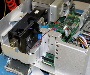
The filtering section of an OSA is the most complex and fragile part of it as, to deliver measurements in the pico-meter range, mechanical accuracy must be in the same range.
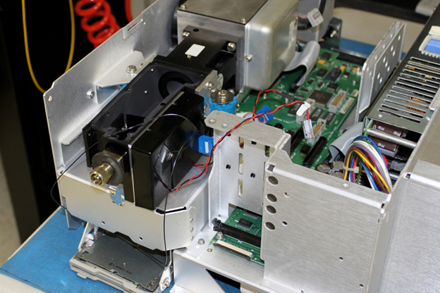
Fig2: Black part is an opened Optical filtering section in an Agilent-HP 86142B OSA